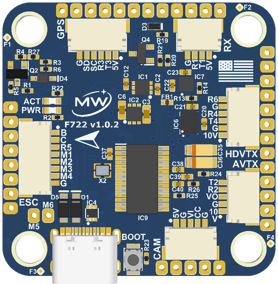
ESC connector
| Pin | Signal |
|---|
| 1 | VIN / VBAT |
| 2 | ADC CURR |
| 3 | UART5 RX |
| 4 | ESC1 |
| 5 | ESC2 |
| 6 | ESC3 |
| 7 | ESC4 |
| 8 | GND |
Camera connector · CAM
| Pin | Signal |
|---|
| 1 | 5 V |
| 2 | GND |
| 3 | VI |
| 4 | CC |
| 5 | GND |
Analog video connector · AVTX
| Pin | Signal |
|---|
| 1 | 10 V |
| 2 | GND |
| 3 | VO |
| 4 | UART2 RX |
| 5 | UART2 TX |
Digital video connector · HDVTX
| Pin | Signal |
|---|
| 1 | 10 V |
| 2 | GND |
| 3 | UART4 TX |
| 4 | UART4 RX |
| 5 | GND |
| 6 | UART6 RX |
Check the video system's own connection guide and power requirements before selecting a harness.
Receiver connector · RX
| Pin | Signal |
|---|
| 1 | 5 V |
| 2 | UART1 TX |
| 3 | UART1 RX |
| 4 | GND |
GPS connector
| Pin | Signal |
|---|
| 1 | 5 V |
| 2 | UART3 TX |
| 3 | UART3 RX |
| 4 | I²C SCL |
| 5 | I²C SDA |
| 6 | GND |
Before connecting a peripheral
Use the board schematic to establish TX/RX signal direction from the flight controller's perspective. For a conventional full-duplex UART connection, the controller's TX connects to the peripheral's RX and vice versa; single-wire or inverted protocols need their own verified wiring.
Confirm supply voltage separately from signal voltage. The presence of a 5 V or 10 V power pin does not establish the voltage tolerance of adjacent signal pins.
Continue to UART mapping and the MW F722 power notes.